
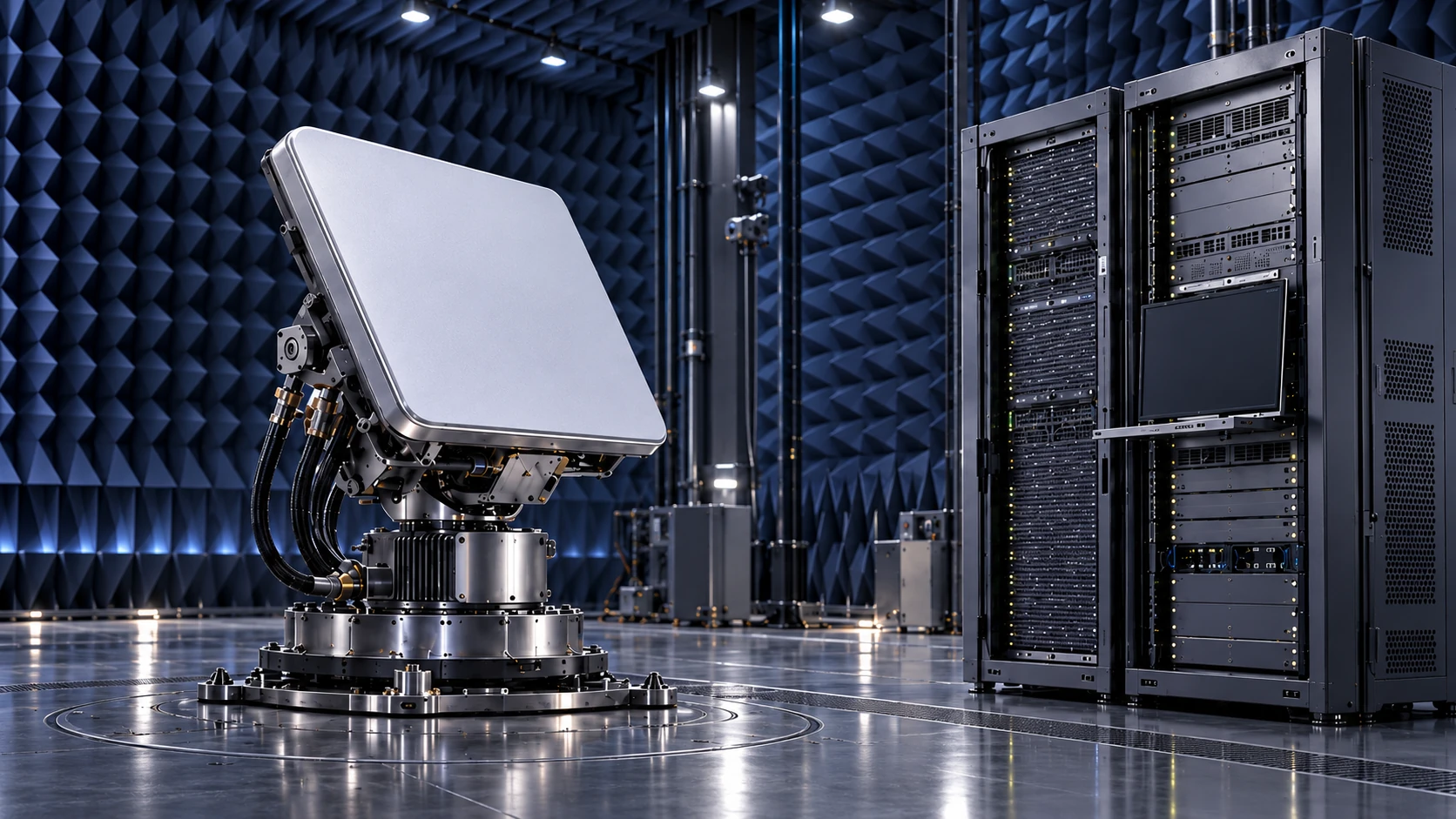
Programmed RF conditions describe the path. The terminal, network and application provide the response you need to observe.
Start with the decision,
then choose the test.
A terminal may attach successfully while an application still retries, misses a useful window or recovers slowly after an interruption. Each observation answers a different question. A test becomes easier to interpret when the decision is explicit before the equipment and scenario are selected.
For a receiver change, the question may concern acquisition or tracking under a declared residual timing or frequency error. For a network integration, it may concern attachment and useful traffic through one selected UE–gNB pair. For an application, it may be completion before a deadline. The relevant observable and supporting tools change with that choice.
Investigating the radio?
Use the actual compatible radio implementation and defined RF conditions. Observe its counters, lock, acquisition and recovery with appropriate instrumentation.
Investigating a service timer?
An IP or protocol-level experiment may answer a delay/timeout question more directly. Add an RF chain when actual radio behavior matters to the decision.
One label does not
define the topology.
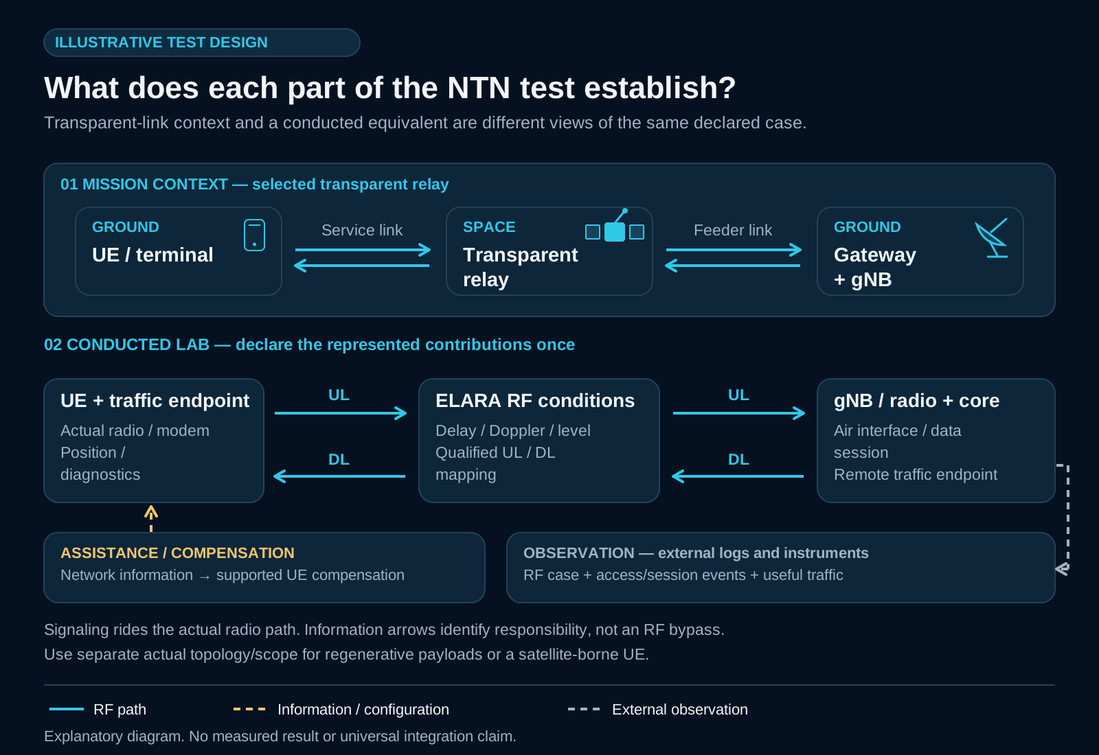
“5G NTN” identifies a family of arrangements, not a single diagram. State where the UE and gNB sit, which functions are on the satellite, the service and feeder paths, and which parts the laboratory setup actually exercises.
 Explore the diagram
A space relay connects a ground UE and ground-side gNB through the declared service and feeder paths.
Some radio-access functions are onboard. Declare the actual split rather than moving the gNB symbol into an otherwise unchanged test.
The 5G Nanosatellite research places a UE on the spacecraft and communicates with terrestrial gNBs. Its endpoint arrangement is different.
For the conducted setup, identify both uplink and downlink RF directions, the applicable release, radio configuration, interfaces and occupied bandwidth, and how any conversion is provided. Assign each represented propagation contribution once; omitting a feeder contribution and counting it twice are different configuration errors. Broadband NR NTN and NB-IoT/eMTC NTN are different endpoint families.
A conceptual link drawing does not establish equipment compatibility, coherent MIMO, flight operation or a complete end-to-end network implementation.
Keep the responsibilities
visible.
Channel conditions, network assistance, terminal compensation and useful traffic are related, but they are supplied and observed by different parts of the testbed.
| Part of the chain | Its role | What to declare |
|---|---|---|
| Compatible RF-channel path | Apply the supported programmed delay, Doppler and signal-level conditions. | UL/DL paths, configuration, reference plane and commanded profile. |
| UE, gNB and assistance sources | Provide the actual stack, signaling, satellite/position inputs and compensation behavior. | Release, architecture, endpoint versions and the selected assistance/update arrangement. |
| Core, traffic and application endpoints | Establish the intended service and generate/receive the useful workload. | Session, traffic direction, offered load, deadline and completion rule. |
| External instruments and records | Observe the result and align RF, protocol and application events. | Timebase, counters, logs, measurement method and relevant uncertainty. |
For example, an NTN assistance message such as SIB19 belongs to the actual network implementation; an RF channel emulator does not become its signaling source. SIB19 and other over-the-air messages still travel through the actual downlink. A separate information arrow identifies responsibility, rather than a signaling path that bypasses RF.
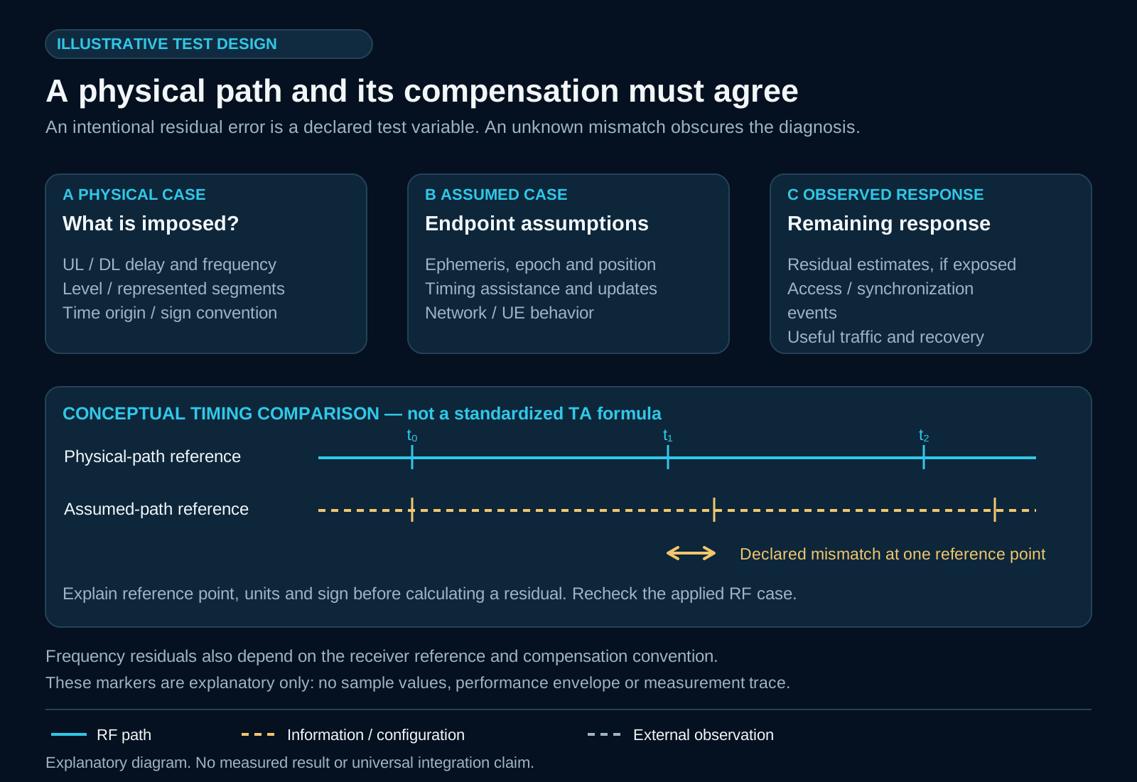
For a residual-error experiment, distinguish the physical path, the assistance/position/epoch assumed by the system and the compensation the UE/network actually apply. Declare the reference point, one-way or round-trip meaning, time origin and sign convention. Avoid applying the same correction in profile generation and endpoint configuration unless that is the declared experiment.
 Explore the diagram
Make the baseline
worth comparing.
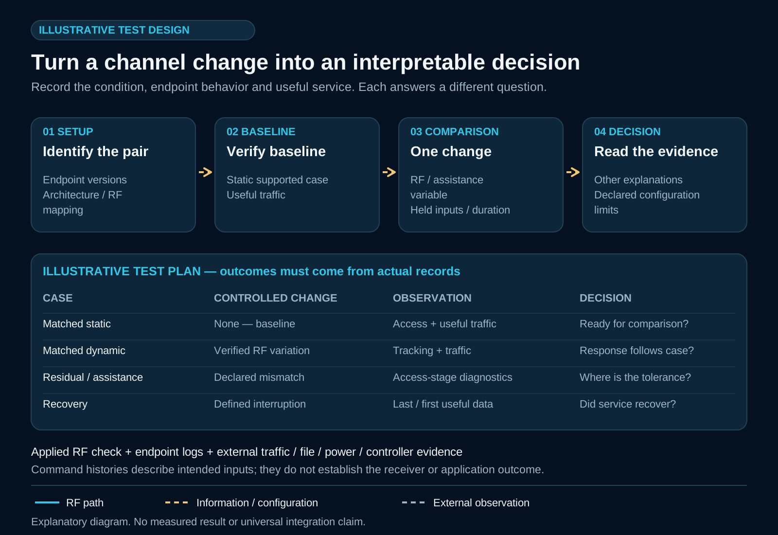
First establish the intended static path with the selected endpoints. Verify attachment and, where relevant, a session and useful traffic. Record the versions, assistance configuration, RF settings, offered load and observation window. Confirm that the instruments can observe the behavior the comparison is meant to reveal.
Change one declared factor at a time when you want to interpret its effect. Reusing a scenario makes the programmed inputs comparable; it does not guarantee bit-for-bit identical RF waveforms, endpoint state, traffic timing or measured output. Preserve enough configuration and raw evidence to explain the differences that remain.
Before the first comparisonUse the test-planning checklist ↗Choose the condition.
Name the observation.
The examples below are proposed test cases, not reported ELARA measurements or completed integrations. Select only conditions supported by the actual setup, then choose a range and acceptance criterion from the system requirement.
| Test question | Declared change | Observe externally |
|---|---|---|
| Does the nominal path work? | Matched static RF/assistance baseline. | Attach, session establishment and useful traffic. |
| Can the receiver follow a changing path? | Supported dynamic delay/Doppler profile with matched assistance. | Acquisition/tracking, traffic continuity and recovery. |
| What happens when compensation is imperfect? | A declared residual timing/frequency offset or assistance-age case. | Attach time/success, errors and recovery of the selected implementation. |
| How does the service respond to reduced margin? | A supported signal-level condition while other factors are held. | Radio counters, retries and useful delivery. |
| What recovers after an interruption? | A defined interruption supported by the actual path/control setup. | Radio recovery, session state and application completion. |
A handover or access change needs the actual additional cell/access, network logic and signaling. A changing RF path alone does not implement a handover. Distinguish NR cell mobility, a TN/NTN access change and application continuity when describing what the test establishes.
Follow the chain
past attachment.
 Explore the diagram
Write a completion rule that matches the application. For a data-transfer question, a verified complete file is different from transmitted bytes. For an access question, successful attachment is different from a usable bearer. For recovery, identify the interruption, the endpoint state and the point at which useful service resumes.
Use command history to state the intended condition, and verify relevant applied behavior independently. Control values alone do not prove the signal seen by the receiver. Align timestamps and units across the records you compare; a one-way-latency claim needs a justified cross-end clock relationship, while a round-trip observation measures a different quantity.
Report the denominator and observation interval for rates or success fractions. Keep failed or incomplete outcomes visible. A clean summary should allow another engineer to see the actual configuration and what the measurement does and does not establish.
Match the conclusion
to the evidence.
A result belongs to its endpoints, configuration, conditions and measurement method. It may support a firmware setting, an integration decision or a more focused next test. It does not automatically establish universal interoperability, certification, a full mission replica or the performance of another release.
ELARA's role is to contribute a qualified RF-channel path within the selected setup. Network assistance, traffic, handover logic and application measurements remain with the systems that provide them. This separation makes the contribution useful and the conclusion easier to assess.
A test-design method and illustrative architectures. It is not a conformance procedure, a compatibility statement for every UE/gNB pair or a report of a new physical experiment.
Different projects.
Different questions.
Use research examples for the question they actually address. The University, consortium and company roles, the project stage and the specific channel-emulation contribution remain distinct.
A satellite-borne UE and ground-gNB research arrangement, with conducted ground evaluation before the planned space mission.
↗ ETHERA TN/NTN research context: distinguish the initial ELARA test environment from the later consortium-reported HIL showcase.
↗ MiRAGEVirtualised-gateway research examining satellite-channel conditions and processing workload. Public project objectives remain separate from released outcomes.
↗ SPAICEA separate AI payload/adaptive-beamforming story, with a published historical ChEM/ELARA test-chain role.
↗The completed 5G-GOA and 5G-LEO work provides related protocol and software research foundations. Their project pages explain the earlier GEO/LEO questions, participants and source-specific laboratory context.
Sources and
practical next steps.
This guide is an editorial explanation of a test method. The standards discussion uses selected Release 18 context, not a claim to the newest specification or a conformance recipe. For actual integration settings, use the applicable specifications and the selected implementation's documentation.
- ETSI TS 138 300 V18.8.0 / 3GPP TS 38.300 Release 18 — sections 16.14.2–16.14.3
- OpenAirInterface — How to run an NTN configuration (implementation-specific documentation)
- OAI 2024 contributor abstracts — 5G Nanosatellite context
- ETHER — project-reported final showcase
- ESA — MiRAGE project context
- SPAICE 2024 — published testbed manuscript
Prepared by LuxWave. Illustrative diagrams explain roles and test design; project-specific results remain attributed to their cited sources. Updated 26 October 2026.